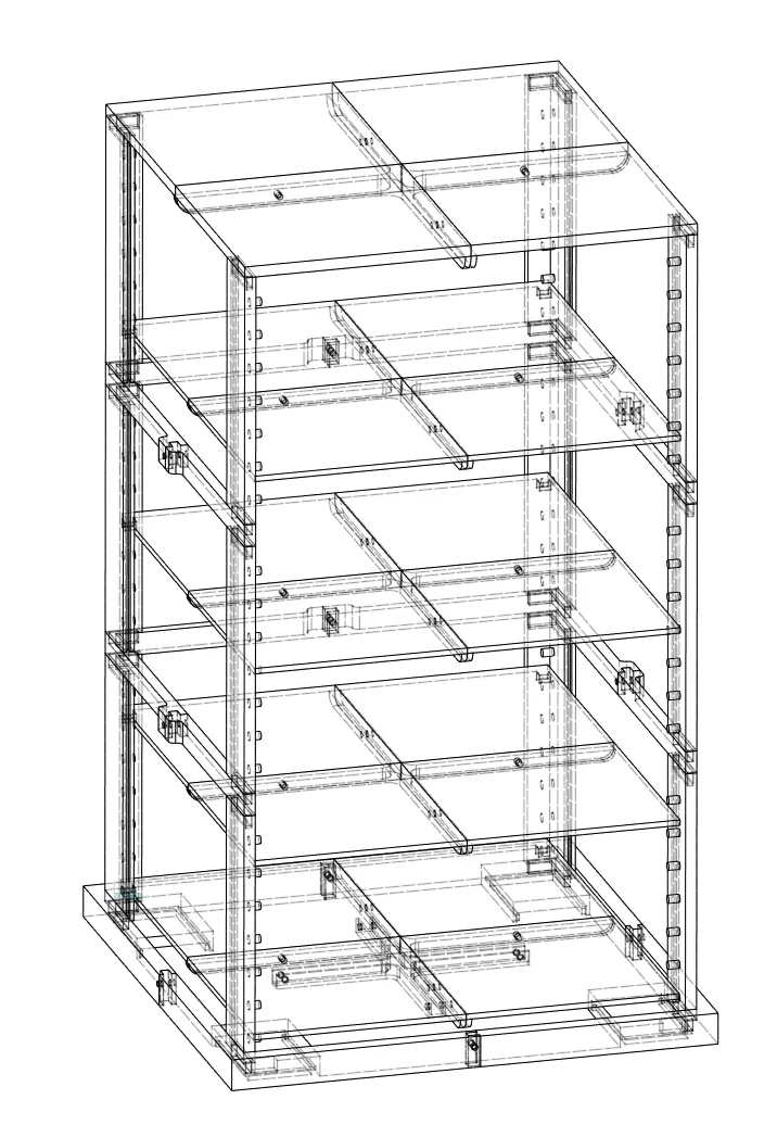
A STEP file brings clean, accurate geometry into a render, plus the assembly tree and part names, and usually not much else. Colours sometimes survive. Materials, textures, decals, cosmetic threads and any UV mapping never do. If you know that before you export, a STEP file to render job goes smoothly. If you don't, the first day of the job is spent rebuilding things you assumed were "in the file".
I get a STEP file on most product jobs now, and I'd say 80% of them import without drama. The other 20% are where the hours go.
What a STEP file actually carries
STEP (ISO 10303) describes boundary-representation solids: exact surfaces, edges and faces, with no polygons at all. That's why engineers like it and why it's the safest neutral format to send between CAD packages. The common flavours are AP203, AP214 and AP242. AP214 and AP242 can carry colours per face or per body, and AP242 can carry product manufacturing information too, though no renderer I use reads PMI and I wouldn't want it to.
What you can rely on after import: the shapes, the hierarchy (assembly, sub-assembly, part), the part names if whoever exported it named things properly, and the units, mostly. A sensor enclosure I received last spring came through as 212 bodies, each with a sensible name like "lid_upper" and "gasket_main". That's a gift. I've also had a 40-part pet feeder arrive as "Body1" to "Body40" in a flat list, which meant clicking every part to work out what it was before I could assign a single material.
What gets lost on the way into a renderer
Appearances are the big one. The brushed aluminium, the soft-touch plastic, the walnut veneer you set up in Fusion 360 or SolidWorks: none of it exists outside that program. At best a STEP file tells me a face was grey (128, 128, 128). I treat any colours that do come through as a labelling system rather than a look.
Then the smaller losses:
- Decals and logos applied as appearances in CAD vanish completely. Send the artwork as a separate SVG or high-resolution PNG.
- Cosmetic threads disappear. A threaded boss becomes a plain cylinder, which is fine for 95% of shots and wrong for a macro of a bottle neck.
- Sketches, construction planes and configurations don't travel. You get one state of the model, the one active at export.
- Text that was embossed as a feature survives, because it's real geometry. Text that was an appearance doesn't.
Nobody warns you about the last one, and it catches people every few months.
Tessellation: where STEP geometry turns into polygons
Renderers don't draw exact surfaces. They draw triangles. So somewhere between your STEP file and my render, the B-rep gets tessellated, and the settings of that step decide whether a fillet looks smooth or like a stop sign.
KeyShot imports STEP directly and asks for a tessellation quality. Blender has no native STEP importer, so for Cycles work I convert in Fusion 360 first, exporting OBJ or FBX with refinement set high, or use an add-on when the assembly is simple. Either way I'm choosing a chordal tolerance and an angle tolerance. On a typical handheld product, fine settings land somewhere around 1.5 to 3 million triangles. Coarse settings might give 200,000, and that's the version where a 2 mm edge fillet shows visible facets in a close-up at 4000 px.
Too fine is a problem too. I once imported a small kitchen appliance at the finest KeyShot setting and got close to 18 million triangles, most of them spent on internal screws and a PCB nobody would ever see. Viewport speed dropped to a crawl. I deleted the hidden internals, re-tessellated the visible shell finer than before, and ended at about 2.4 million. Better looking and faster.
The counter-intuitive bit: the smoothest render doesn't come from the highest tessellation everywhere. It comes from fine tessellation on the curved, visible, glossy surfaces and coarse everywhere else, plus proper shading normals. Glossy plastics expose faceting far more than matte ones, because a reflection bends at every triangle edge.
Normals, scale and the other quiet problems
Units are the one I check first. STEP stores units, but I still see models arrive 1000 times too big or too small after a conversion step somewhere. A 120 mm bottle that imports as 120 metres renders with the wrong depth of field and wrong light falloff, and it takes a minute to fix if you notice and an afternoon if you don't.
Shading normals are the next. A clean STEP tessellation gives smooth normals on curved faces and hard edges at sharp corners, which is what you want. A badly converted mesh gives you smoothing across sharp edges, so a crisp chamfer on a lid looks melted. In Blender I usually fix that with an auto-smooth angle around 30 degrees, then check by eye.
Small gaps matter more than people think. Two parts that touch perfectly in CAD can render with a thin black seam if the tessellation of each face lands slightly differently. Is that a defect? On a hero shot, yes. I'll often nudge a part by 0.05 mm or merge bodies that are really one visible piece.
Why STEP still beats the alternatives for me
You could send an STL. I'd rather you didn't. STL is already tessellated, usually at whatever resolution suited the 3D printer, it has no hierarchy, no part names and no colours, and every part arrives welded into one blob or as separate files with no relation to each other. Converting it back into something renderable costs real time.
Native files (SLDPRT, F3D, IPT) carry more, but I can only open some of them and the versions matter. A STEP export from SolidWorks or Fusion 360 is the boring middle option that works nearly every time, which is exactly why it's my default. If your team works in SolidWorks and you need files going the other way too, I've written up how I handle SolidWorks-compatible CAD from Fusion 360.
What I'd actually ask you to export
My short list, after a few hundred of these:
Export AP214 or AP242 STEP, as one assembly file rather than one file per part. Name the bodies before you export, even roughly. Strip out what will never be seen in any shot: fasteners hidden inside the housing, cable runs, the PCB if the case is opaque. If you can't strip them, tell me which sub-assemblies are hidden and I'll do it.
Then send the things STEP can't carry. A short material list ("lid: matte black PC, ring: anodised aluminium, bead blasted") does more for the final image than any setting I can choose. Logos and labels as vector files. One or two photos of a real sample if one exists, even from a phone, because a photo of the actual texture beats any description.
And if the model was built for manufacturing rather than display, that's normal. Most of my work on CAD design services jobs starts from models like that, and I'd rather have accurate engineering geometry with ugly names than a pretty mesh that's 3 mm off.
When the files are right, the rendering stage is the easy part. Have a look at how I run 3D product rendering from CAD, and if you have a STEP file and a deadline, send it over and I'll tell you honestly what it needs before you pay for anything.