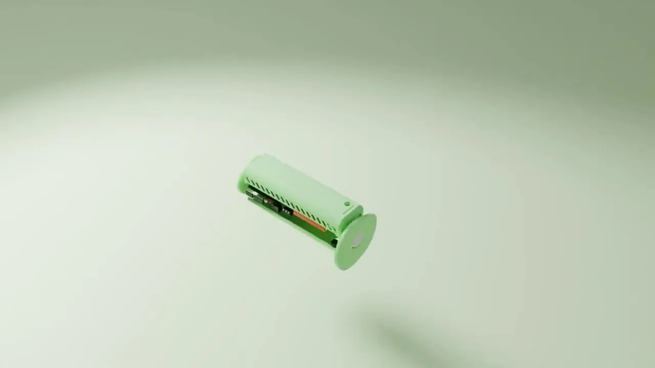
A product cutaway render removes part of the housing so you can see the mechanism, the insulation or the electronics inside, while everything else stays exactly where it sits in the real product. Done well, it explains a product in one image. Done badly, it shows an interior that couldn't exist: parts floating in air, a cut that slices through screws at convenient angles, walls that are suddenly hollow. The difference is mostly discipline, not software.
I've made a fair few of these, from barrel saunas to sealed sensor enclosures to a pet feeder with a motor and auger hidden behind a glossy shell. Here's how I approach them.
Cutaway vs exploded view vs X-ray
These three get confused, so it's worth being precise. An exploded view rendering pulls parts apart along their assembly axes. It's great for showing what's in the box and the order things go together, but it destroys the spatial relationship between parts. You can't see that the gasket presses on the lid because they're 40 mm apart in the picture.
A cutaway keeps every part in its assembled position and removes material. The relationships stay true. You see that the PCB sits 3 mm above the floor of the housing, that the cable runs under the battery, that the insulation fills the wall cavity of a sauna cabin all the way to the roof.
An X-ray or ghosted view keeps the outer shell but makes it transparent or semi-transparent. It works when the outside shape matters as much as the inside. It struggles when there are many overlapping layers, because three translucent surfaces on top of each other turn into grey soup.
Which one? Ask what the viewer needs to understand. Order of assembly: exploded. How parts sit relative to each other: cutaway. Where the inside is relative to the outside shape: ghosted.
The cut plane is the whole design
Most of the decisions in a cutaway happen before any lighting. Where does the cut go, and what shape is it?
A single planar section through the middle is the honest default. It's what an engineer would draw on a section view, and nobody can accuse it of hiding anything. But it often cuts through the wrong things: a shaft gets sliced lengthwise (fine), a row of screws gets sliced in half (distracting), and the one sensor you wanted to show sits 5 mm behind the plane and disappears.
The usual fix is a stepped or quarter cut. Remove a 90° wedge from a round product, or step the plane so it passes through the feature you care about. That's legitimate. Engineering drawings use offset sections for exactly this reason.
What isn't legitimate is a cut shape that follows the interesting parts like a cookie cutter, leaving the outer wall intact around them so the inside looks more spacious and tidy than it is. I've had requests for that. I push back, because the first person who opens the real product will notice the gap between the brochure and the box.
My rule: the cut should be describable in one sentence. "A quarter section through the vertical axis." "A step cut through the left wall and the heater." If explaining the cut takes a paragraph, it's probably lying.
What not to cut
Here's the counter-intuitive part. In a good cutaway, many parts that physically sit on the cut plane are left whole.
Engineering drawing convention says you don't section fasteners, shafts, pins, ribs along their length or ball bearings. Cutting a bolt in half adds nothing and makes the image noisier. The same applies in a render. When I set up the Boolean, I exclude screws, cables, PCBs (usually), motors, and anything that reads better whole. The housing, walls, insulation and liners get cut; the functional bits stay intact and appear to sit in the opening.
It looks slightly odd if you think about it hard.
Nobody does. It reads instantly.
The exception is when the inside of that part is the point: the windings in a motor, the layers in a battery pouch, the foam stack in a mattress. Then you cut it, and you probably need a separate cap material to make the layers visible.
Cap faces, colour and the hatching question
When you cut a solid in Blender with a Boolean, the new faces are just more surface of the same material. A cut through 2.5 mm of black ABS gives you a 2.5 mm strip of black ABS edge, which is invisible against a dark interior. That's the most common reason a cutaway looks confusing.
So I give cut faces their own material. Usually a flat, slightly lighter or slightly saturated version of the part's colour, or a consistent accent colour for every cut face across the image. A strong red or orange on all cut faces is a classic technical illustration trick, and it works because the eye instantly understands "this is where the knife went".
Some clients want hatching like a drawing. It's possible with a procedural stripe texture mapped in object space, at around 45° with lines every 1.5 to 2 mm at product scale, but in a photoreal image it often looks fussy. I'd reserve it for images that sit next to technical drawings in a manual.
A practical detail: cut faces should be truly flat. If the CAD tessellation is coarse, the cap on a cylinder will show facets. I re-import the STEP at a finer tolerance (around 0.01 mm chord deviation for small consumer products) before cutting, or the cap edge looks like a 24-sided coin. My notes on what survives a STEP import cover that in more detail.
Keep the physics honest
Once you cut the housing, things that were held by it look unsupported. A battery that clips into ribs on the removed half now floats. A cable routed through a removed clip hangs in space.
There are two fixes.
Either move the cut so the supporting features stay visible, or keep a sliver of the supporting structure (a rib, a boss) uncut, which is the same convention as with fasteners. What you don't do is quietly delete the clips because they cluttered the frame.
Last year I rendered a barrel sauna cutaway for a manufacturer's catalogue. The first version cut through the stave wall and showed the bench and heater beautifully, but the bench supports were on the removed side, so the bench looked cantilevered off one wall. A sauna builder would spot that in a second. I rotated the cut plane by about 30° so two supports landed in the visible half, and the image went from impressive to believable. The cutaway sauna on my sauna visualization page uses the same idea.
Lighting matters for honesty too. A cut opening is a dark cavity in real life. If you flood it with light to show the inside, use an area light that could plausibly exist (like a softbox off camera) rather than invisible lights placed inside the product. Light leaking from nowhere makes the interior feel like a separate composite.
Small things that make it read
A few details I set every time, because they save a revision round:
- A slight bevel (0.2 to 0.3 mm) on the cut edge, so it catches a highlight and separates from the interior.
- Ambient occlusion detail left in, not cranked up. Contact shadows tell the eye parts are touching.
- Camera at about 30 to 40° above the cut, never square on. Square on looks like a drawing; angled shows depth.
- Interior parts in their real colours, even when they're dull. Repainting a green PCB blue for the brand palette is a small lie that engineers notice.
Render time in Cycles isn't the problem people expect. A typical cutaway at 3000 × 3000 px with 512 samples and denoising runs 10 to 25 minutes on my machine. The slow part is setup: building the cut, fixing caps, deciding what stays whole. On a medium-complex product that's 3 to 5 hours before the first test render.
What I'd actually do with your product
If your goal is marketing, one cutaway is usually enough: hero exterior shot, then the cutaway as the second or third image that answers "what's inside that justifies the price?". On a product page that's the image people zoom into. Make one, make it clean, use a single cut plane or quarter section.
If your goal is technical (a manual, a trade fair panel, an investor deck explaining the mechanism), do the cutaway plus an exploded view. They answer different questions and work well side by side.
And send the real CAD. A cutaway from a visual-only model, where internals were never modelled, isn't a cutaway. It's an illustration of what someone imagined was inside. For anything where the inside matters, I work from the engineering STEP, and if parts are missing I'd rather flag it than invent them (that's where the mechanical engineering side of my work earns its keep).
Have a product with an interesting inside? Send the STEP file and tell me what one thing the viewer should understand. I'll tell you which cut shows it best before anything gets rendered, as part of my 3D product rendering work, or just get in touch.